Our kits come in two levels.
The basic kit simply replaces the stock regulator. The stock feed lines and connections are
retained, and the stock return line is used.
This is suitable for a car running a pump larger than stock, and a car
with power needs that do not exceed what you can get through the stock 8 mm OD
feed line. The parts included make it a
bolt-on system. You simply remove the
stock regulator and some of the stock plumbing, and replace it with the parts
we supply. The regulator screws to the
firewall, and the lines/connectors hook directly to the stock rails and return
line. See the installation instructions
and pictures below. All parts are
anodized aluminum, all fittings are AN style, and all fuel lines are braided
stainless style.
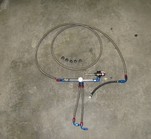
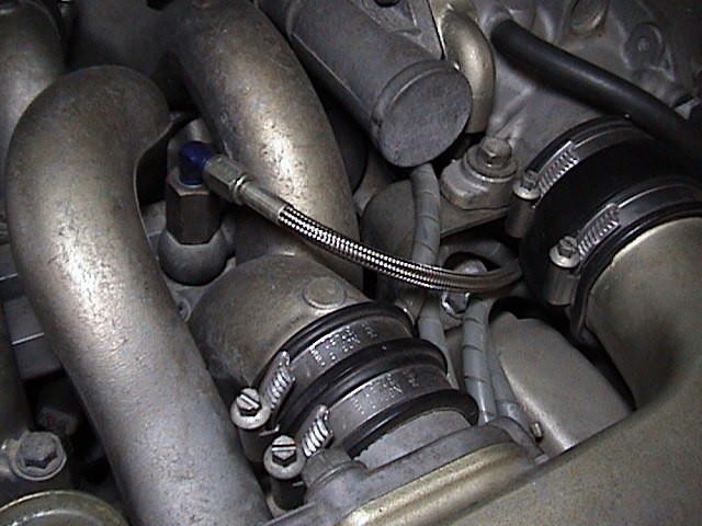
Our high-flow kit adds 7/16” ID (-8 braided) feed lines, an adaptor to
hook directly to the fuel pump, a high-flow filter, optional underhood pressure
gauge and dual feeds for the rails, i.e. 1 feed line per rail, in a ‘dead end’
configuration, similar to what is used on many race cars. This is in comparison to the stock rail feed
configuration (retained in the basic kit) which is in series, i.e. the first rail
is fed, and then a line connecting the two rails feeds the 2nd rail,
then the fuel goes through the regulator, and back to the tank. In other words, all the fuel that the pump
produces will flow through the rails (other than what is delivered by the
injectors). With the dead-end system,
the only fuel that goes to the rails is what is used by the injectors. The excess fuel is returned to the tank by
the regulator before it gets to the rails.
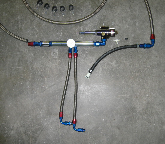
This reduces heating of the fuel in the tank, (since the fuel does not
run through the hot rails before going back to the tank) and with a dedicated
feed line for each rail, makes sure that the rail pressure in each rail is the
same, and there are no restrictions in getting fuel to each rail. Instead of a single 8 mm OD line feeding 6
injectors, you have two –6 AN hoses (11/32" ID) feeding 3 injectors
each. See the photos of our high-flow
kit at the end of this page. Note that
the stock return line itself is not a restriction (verified through testing),
so we see no need to upgrade the stock return line, even when running a
full-sized feed line and a fuel pump at full voltage. NOTE – if you want
a high-flow kit, but can’t afford it now, go ahead and get the basic kit for
now, as we offer an upgrade from the basic to hi-flow (i.e. the high-flow feed
setup) that is priced so the cost of the basic kit + the upgrade will not cost
any more than the outright purchase of the hi-flow kit AND you get the main
benefit of the kit NOW, i.e. a steady relative fuel pressure.
Installation instructions for the basic kit (These are pictures of an
early kit – current kits are a little more polished, and don’t have the brass
elbow fitting on the front, refer to the hi-flow kit pics for a more accurate
picture of the regulator). Please also note that due to rising parts costs, we have switched to a 'house brand' regulator. The name brand regulator shown in the photos is still available for the upgrade shown in the price list:
0. De-pressurize the fuel
system.
1. Remove banjo bolt from
assembled regulator and set aside.
2. Remove the cross-over tube
from the intake.
3. Remove the stock regulator
and clean the rail connection. You will
need to grind down a cheap 7/8” or 22 mm wrench to do so, unless you want to
remove the intake, or remove the upper inner cam cover. Some have had luck with specialized
Vice-Grips instead of the wrench
http://panamapat.no-ip.info/SHO/shonutfpr/040703102657003.jpg
or a crow’s foot wrench
http://hosting.superhighoutput.com/twr/Terry/josh/100_3087.JPG
4. Unhook the return fuel
line. Use a Ford fuel line tool.
5. Remove the short piece of
line that went between the regulator and the return line. This entails removing all three bolts and
replacing 1 to hold the supply line in place.
If the 3rd one has not been removed in the past, you may have to remove
the intake to get at it to apply enough torque to the bolt to break it loose,
as it’s near impossible to get a wrench on it properly. If it has been removed before, it should
come out with your finger tips once you get it loose with a wrench, even when
used at the improper angle.
6. Remove the BAP sensor.
7. Remove the BAP bracket.
8. For 90-95 flip the BAP
bracket upside down and install as per pic.
You may need to grind a little off the tab that mounts onto the crash
sensor. Only one bracket bolt is used
(the one from the crash sensor).
http://www.shonutperformance.com/FPR_closeup.jpg
http://www.shonutperformance.com/AC_routing.jpg
9. For 89, bolt the BAP to the
fuel pump resistor bracket.
10. Loosen (but do not remove)
the allen head screw that holds the modified FPR bracket in place. If the bracket is not attached, install it
as per the picture (note that one screw does not go into anything.)
http://www.shonutperformance.com/AC_routing.jpg
11. Thread braided line as per
picture - between A/C line and firewall, to the passenger side of the
passenger-side intake bracket, between the feed line and the intake
bracket, under the feed line, and finally to the Rail.
http://www.shonutperformance.com/AC_routing.jpg
http://www.shonutperformance.com/FPR_closeup.jpg
http://www.shonutperformance.com/FPR_overall.jpg
12. Loosely install the Banjo
bolt – install the small washer between the banjo and the rail, and the large
washer between the bolt and the banjo.
13. Position 90 at the braided
end 1/8" from the A/C line on all sides, as per AC routing picture.
14. Mark position of bracket on
firewall, making sure it is flat against the firewall.
15. Remove bracket from FPR and
fasten to firewall with supplied screws, as per picture, according to
marks. Make sure there is enough room
between the BAP bracket and the hex adjustment screw to insert an allen wrench. IOW, don't crowd the BAP bracket with the FPR.
http://www.shonutperformance.com/FPR_closeup.jpg
16. Attach FPR to bracket,
making sure that braided hose is in the correct spot as per picture before
tightening allen screw for bracket.
http://www.shonutperformance.com/AC_routing.jpg
17. Put a drop of oil on the
return line connector o-rings and insert into the end of the supplied adaptor
on the end of the regulator.
18. Tighten banjo bolt, but DO
NOT over-tighten it. If you
over-tighten it and break it, you can get a new bolt and washer EAR-997591ERL
from www.summitracing.com If necessary, the 90 degree fitting (and
banjo fitting) will rotate internally to make sure that the banjo fitting is
flat on the rail.
19. Tee into secondary vacuum
line at back of engine for FPR reference line.
Re-use stock FPR reference line and connect from the tee to the FPR
reference port.
20. Cap stock regulator nipple
near crossover at front intake plenum with supplied cap (originally installed
on FPR reference port).
21. Re-install intake cross-over
tube.
22. Turn key on and check for
leaks.
23. Cycle key a few times and
re-check for leaks.
24. Start car and check for
leaks. (Car may not run properly until
the fuel pressure is set, see below)
25. Turn car off and verify that when the key is
turned on (but not started) that the fuel pressure rises to 39 psi. Adjust as required - loosen the lock nut,
and turn the threaded adjuster with an allen key. The best way to adjust is to ground the fuel pump test connector
in the EEC self test plug (see pic in the link below), and turn the key on, so
the pump is running, but the car is not, then make your adjustment. Always approach the pressure from below,
i.e. start at 38 and work up to 39, not the other way around. Do NOT adjust the pressure with the engine
running (yet).
http://www.shotimes.com/php-bin/pics/eec.gif
26. Double check the pressure reading again with the car running, but the
FPR reference line disconnected and plugged.
The car may run rough (rich) for a bit.
Make sure that the reading is still 39 psi. Adjust as necessary (may require 0.5-1 psi adjustment).
27. Plug the FPR reference line back into the FPR, and look for the fuel
pressure to drop by ½ of your engine vacuum reading (see below). For example, you should see 31 psi at the
rail with 16 inches of vacuum (-8 psi) at idle. Do NOT adjust the pressure with the engine
running and the FPR reference line attached to the FPR. If you think it still needs adjustment, go
back to step 26.
28. Enjoy!
Additional pictures of the basic kit on
client’s cars
Pat McGrath
http://panamapat.no-ip.info/SHO/shonutfpr/Page.html (braided return hose routed incorrectly,
should be on the passenger side of the passenger-side intake bracket, and not
under the ‘middle’ of the intake, which could lead to a sharp bend – correct
routing shown here: http://www.shonutperformance.com/AC_routing.jpg
http://www.shonutperformance.com/FPR_overall.jpg
).
Jason Zuress
http://memimage.cardomain.net/member_images/9/web/225000-225999/225912_475_full.jpg
http://memimage.cardomain.net/member_images/9/web/225000-225999/225912_476_full.jpg
http://memimage.cardomain.net/member_images/9/web/225000-225999/225912_477_full.jpg
http://memimage.cardomain.net/member_images/9/web/225000-225999/225912_478_full.jpg
http://memimage.cardomain.net/member_images/9/web/225000-225999/225912_479_full.jpg
http://memimage.cardomain.net/member_images/9/web/225000-225999/225912_480_full.jpg
http://memimage.cardomain.net/member_images/9/web/225000-225999/225912_481_full.jpg
Terry Richard
http://hosting.superhighoutput.com/twr/Terry/josh/100_3087.JPG
http://hosting.superhighoutput.com/twr/Terry/josh/100_3090.JPG
http://hosting.superhighoutput.com/twr/Terry/josh/100_3092.JPG
http://hosting.superhighoutput.com/twr/Terry/josh/100_3095.JPG
http://hosting.superhighoutput.com/twr/Terry/josh/100_3097.JPG
http://hosting.superhighoutput.com/twr/Terry/josh/100_3099.JPG
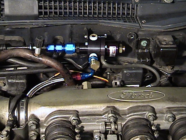
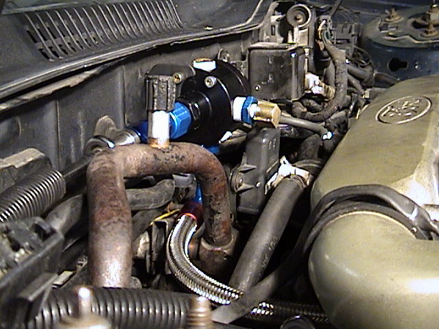
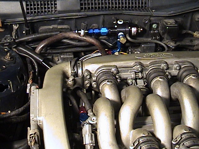
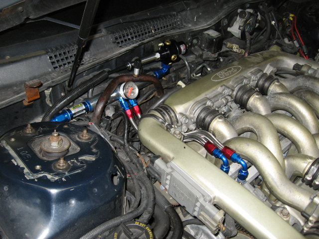
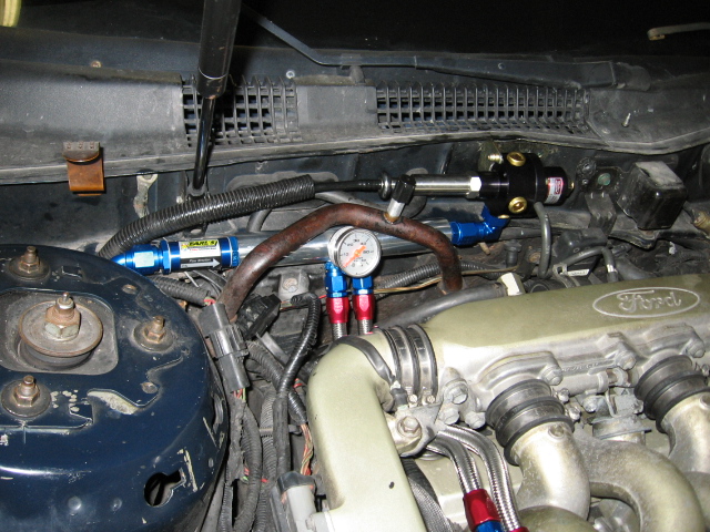
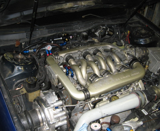
Pictures of a high-flow kit with optional underhood
gauge
(Instructions to come soon, kit replaces stock
feed line and regulator)
http://www.shonutperformance.com/High-flow_FPR.jpg
http://www.shonutperformance.com/High-flow_FPR_closeup.jpg
http://www.shonutperformance.com/High-flow_FPR_overall.jpg
http://www.shonutperformance.com/High-flow_FPR_parts_overall.jpg
http://www.shonutperformance.com/High-flow_FPR_parts_closeup.jpg
Want more tech info? Keep reading …
Why do we offer an aftermarket regulator?
In simple terms, the stock regulator is a restriction for flows seen
with anything larger than a stock fuel pump.
Note that this is not a restriction in flow TO the rails, but a
restriction in flow FROM the rails back to the tank, as the regulator is
plumbed AFTER the rails in the stock configuration. The stock configuration is tank -> pump -> filter ->
feed line -> damper -> rails -> regulator -> return line.
The stock regulator, while a very accurate piece, unfortunately, has
very tiny internal metering passages.
The internal (hidden) metering orifice is 5/64”, or just 0.078” (78
thou). The external exit orifice (the
one you see) is 7/64” or 0.109”.
Needless to say, it’s impossible to push the flow from a 255 lph pump or
even a 190 lph pump at battery voltage* through a 0.078” orifice without it
presenting a restriction to the flow.
If you get a restriction in the flow, you get an excessive pressure drop
across the orifice, or, in other words, a minimum pressure that you can drop
the rail pressure to. The pump is then
overpowering the regulator, and the rail pressure rises too high, see below ….
* If you run the pump at a lower
voltage at lower throttle levels, just like the factory does in the 89 and 90
cars, a 190 may work with the stock regulator without overpowering the
regulator. Of course you need full
voltage at high throttle (just like the factory does for 89 and 90) to ensure
proper fuel flow at high load.
Let’s back up a little bit and see why you need to lower the rail
pressure under certain conditions ….
The function of the fuel pressure regulator is to keep the pressure drop
across the injectors at a constant 39 psi.
In other words, the RELATIVE fuel pressure (across the injector) should
always be 39 psi if the regulator is operating correctly. To verify this, you need to look at both
rail pressure and manifold pressure (or vacuum). The difference between the two should also be 39 psi in order to
get consistent flow from the injector under all conditions. Expressed mathematically, it is 39 psi =
rail pressure - manifold pressure (if
the manifold is at vacuum, then it’s a negative pressure, and vacuum readings
divided by 2 = negative pressure in psi).
OR rail pressure = 39 psi + manifold pressure.
Some real world examples:
16 psi of boost:
rail pressure = 39 psi + manifold pressure, i.e.
55 psi (rail) = 39 psi + 16 psi (manifold). IOW, you should see 55 psi at the rail with 16 psi of boost
11 psi of boost:
rail pressure = 39 psi + manifold pressure, i.e.
50 psi (rail) = 39 psi + 11 psi (manifold). IOW, you should see 50 psi at the rail with 11 psi of boost
6 psi of boost
rail pressure = 39 psi + manifold pressure, i.e.
45 psi (rail) = 39 psi + 6 psi (manifold). IOW, you should see 45 psi at the rail with 6 psi of boost
Key on, engine off (first couple of seconds only after key on, unless
you ground the fuel pump terminal in the self test connector, http://www.shotimes.com/php-bin/pics/eec.gif
), or WOT with 0 vacuum
rail pressure = 39 psi + manifold pressure, i.e.
39 psi (rail) = 39 psi + 0 psi (manifold). IOW, you should see 39 psi at the rail with the key on, engine
off, or at WOT with 0 vacuum
10 inches of vacuum at cruise
rail pressure = 39 psi + manifold pressure, i.e.
34 psi (rail) = 39 psi + (-10/2 psi (manifold)). IOW, you should see 34 psi at the rail with
10 inches of vacuum (-5 psi) at cruise
16 inches of vacuum at idle
rail pressure = 39 psi + manifold pressure, i.e.
31 psi (rail) = 39 psi + (-16/2 psi (manifold)). IOW, you should see 31 psi at the rail with
16 inches of vacuum (-8 psi) at idle
20 inches of vacuum on decel
rail pressure = 39 psi + manifold pressure, i.e.
29 psi (rail) = 39 psi + (-20/2 psi (manifold)). IOW, you should see 29 psi at the rail with
20 inches of vacuum (-10 psi) on closed throttle decel
26 inches of vacuum on decel with a tight engine
rail pressure = 39 psi + manifold pressure, i.e.
26 psi (rail) = 39 psi + (-26/2 psi (manifold)). IOW, you should see 26 psi at the rail with
26 inches of vacuum (-13 psi) on closed throttle decel with a tight engine
The stock regulator has no trouble drawing down the rail pressure to
these low levels with a stock pump, but experience has shown that even a 190
lph pump (at full voltage) is too much for the stock regulator, never mind a
255 lph pump – in other words, the regulator, even when fully open, has enough
of an internal restriction in the main metering passage that the rail pressure
will not drop to the low levels demonstrated above, especially at high vacuum
levels, if a 190 lph pump or higher is used, and the pump overpowers the
regulator. This means that the relative
fuel pressure is too high, and you are flowing too much fuel into the engine at
low load. The EEC will compensate for
this by trimming fuel, remember the compensation, and lean out the rest of your
fuel tables by applying leaning long term fuel trims. This is not a good thing, as once you get closer to 0 vacuum, the
fuel system will work properly, and you will be back to ‘normal’ pressures. However, if the system has been ‘learning
lean’ with the excessive pressures, your close-to-0 vacuum fueling may be now
too lean, like WOT, after the EEC applies what it has learned during higher
vacuum levels.
Let’s say that you see 34 psi at 20 inches of vacuum with a 190 lph
pump. Your relative pressure is rail
pressure – manifold pressure, or 34 psi – (-20/2) = 44 psi, when it should be
39 psi., i.e. it is 5 psi too high, or nearly 15% too high.
Let’s say that you see 39 psi at 20 inches of vacuum with a 255 lph
pump. Your relative pressure is rail
pressure – manifold pressure, or 39 psi – (-20/2) = 49 psi, when it should be
39 psi., i.e. it is 10 psi too high, or nearly 30% too high.
Our aftermarket regulator, on the other hand, does not have this
problem, as the internal passages are MUCH larger. In testing with our aftermarket regulator kit, we’ve been able to
pull the rail pressure down below 20 psi, even with a high pressure 255 lph
pump running at full voltage. This
allows a rock-steady relative pressure of 39 psi (or whatever you set it to …),
regardless of manifold vacuum (or boost).
Note, of course, that the actual rail pressure (which is what most
people measure) will move around with engine vacuum, as it should.
Here is some additional reading:
http://www.mirafiori.com/~thad/fi/fpress.html
http://www.smartworx.com/TurboTekToys/_TipsDisc/0000000c.htm
http://www.flatrater.com/Friends/Regulators/Regulators.htm (not sure why he says that the SHO is not 39
psi, because it is ....)
http://www.theoldone.com/articles/regulator/ (their method if ‘fixing’ the problem is
not recommended, as it compromises ultimate fuel supply capacity)
http://www.corral.net/forums/showthread.php?threadid=418287
Does the above math seem confusing? There’s a way around it to directly read the
RELATIVE fuel pressure, but you need a specific type of gauge setup, namely one
that can read the difference between the manifold pressure and the rail – most
only read the rail pressure directly.
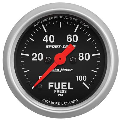
We know of one – the old Autometer 3363 full-sweep electric (electronic)
fuel pressure gauge kits http://static.summitracing.com/global/images/prod/large/atm-3363.jpg
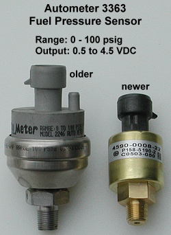
, which have the old gray sender with a nipple on the back of the sender. The new
kits with the same 3363 part number come with the brass-colored or black and
silver senders do not have a nipple – if you have a new kit, find someone with
an older kit and trade senders with them – go to http://www.stealth316.com/2-fp_install.htm
and then come back to this page and click on this picture link http://www.stealth316.com/images/autometer_old&new.jpg
which clearly shows the nipple (you have to go to the page first, or access to
that pic is forbidden).
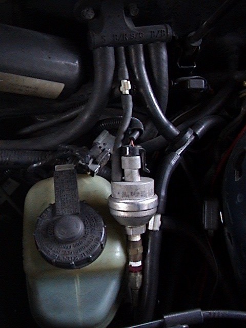
To make it work as a relative pressure sender,
simply remove the little white plug from inside the nipple on the gray sender
and connect the nipple to the vacuum tree or the manifold with a piece of
vacuum hose, and voila, you have a relative pressure gauge, and the gauge
should ALWAYS read 39 psi if your regulator is operating correctly, even with
the engine running, regardless of vacuum or boost. That’s what we do with our car, and with this setup, you can
tell, at a glance (no math and having to look at two gauges) if you have a fuel
pressure issue. If you do this, and if
you have a larger-than-stock pump and stock regulator, chances are that you
will see the relative fuel pressure rise under low loads, as predicted above,
and we’ve seen relative pressures over 50 psi in some cases with the stock
regulator and a larger-than-stock pump.
Here are some pictures of this hookup.
http://www.shonutperformance.com/RelativeP.JPG
http://www.shonutperformance.com/Rail_connection.jpg
http://www.shonutperformance.com/Overall_RelativeP.jpg